ExerArduinoCompElet
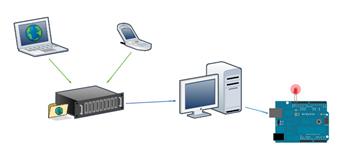
Ardublock is a graphical
programming environment to make programming physical computing with Arduino as
easy as drag and drop.
Importante Instalação http://blog.ardublock.com/2014/12/15/ardublock-introduction-youtube-by-mrromary2/
https://www.youtube.com/watch?list=PLyE44mW92vnu65JOcC0LDVKOo8p3nI4rh&t=14&v=WWATbwdOtF0
|
|
|
|
||||||||||
|
|
|||||||||||
|
Exercícios Arduino
Componentes Eletrónicos |
|
|||||||||||
|
|
ExerArduinoCompElet |
|
||||||||||
|
|
Examples > Digital I/O |
|
||||||||||
|
|
LED – mais curto é
o negativo |
|
||||||||||
|
|
ArduBlocks requisitos de instalação C:\...\...\Documents\Arduino\tools\ArduBlockTool\tool Criar a estrutura de pastas acima e colar o ficheiro do ardublocks dentro da pasta tools
|
|
||||||||||
|
Blink1 9 |
Blink In
most programming languages, the first program you write prints "hello
world" to the screen. Since an Arduino board doesn't
have a screen, we blink an LED instead. The
boards are designed to make it easy to blink an LED
using digital pin 13. Some like the Diecimila and LilyPad) have the LED built-in to the board. On most
others (like the Mini and BT), there is a 1 KB resistor on the pin, allowing
you to connect an LED directly. (To connect an LED to another digital pin,
you should use an external resistor.) LEDs have polarity, which means they
will only light up if you orient the legs properly. The long leg is typically
positive, and should connect to pin 13. The short leg connects to GND; the
bulb of the LED will also typically have a flat edge on this side. If the LED
doesn't light up, trying reversing the legs (you
won't hurt the LED if you plug it in backwards for a short period of time). |
|
||||||||||
|
Blink1 |
Piscar Blink Na maioria das linguagens de programação, o primeiro programa escreve
impressões "Olá mundo" para o ecrã. Desde que placa Arduino não tem um ecrã, vamos piscar um LED em vez
disso. As placas são projetadas para tornar mais fácil para piscar um LED usando
pino digital 13. A perna + curta conecta ao GND ; a lâmpada do
LED será também tipicamente tem uma borda plana sobre este lado
. FILE
> Examples > 01. Basics > Blink |
|
||||||||||
|
Blink1 |
The example code is very simple,
credits are to be found in the comments. /* Blinking LED * ------------ * * turns on and off a light emitting diode(LED)
connected to a digital * pin, in intervals of 2 seconds. Ideally we use pin
13 on the Arduino * board because it has a resistor attached to it,
needing only an LED * * Created 1 June 2005 * copyleft 2005 DojoDave <http://www.0j0.org> * http://arduino.berlios.de * * based on an orginal by H.
Barragan for the Wiring i/o board */ int ledPin = 13; // LED connected to digital
pin 13 void setup() { pinMode(ledPin, OUTPUT); // sets the digital pin as
output } void loop() { digitalWrite(ledPin, HIGH); // sets the LED on delay(1000); // waits for a second digitalWrite(ledPin, LOW); // sets the LED off delay(1000); // waits for a second } |
|
||||||||||
|
|
|
|
||||||||||
|
Blink2 |
Blink Without Delay Sometimes you need to blink an LED (or some other time
sensitive function) at the same time as something else (like watching for a
button press). That means you can't use delay(), or
you'd stop everything else the program while the LED blinked. Here's some
code that demonstrates how to blink the LED without using delay().
It keeps track of the last time it turned the LED on or off.
Then, each time through loop() it checks if a
sufficient interval has passed - if it has, it turns the LED off if it was on
and vice-versa. |
|
||||||||||
|
Blink2 |
Às vezes é preciso
piscar um LED (ou alguma outra função sensível ao tempo), ao mesmo tempo que
outra coisa (como pressionar um botão). Significa que não se pode usar o delay (). Aqui está um código que demonstra como a piscar
o LED sem o uso de delay (). Ele mantém o controlo
da última vez que o LED esteve on ou off. Então, cada vez que através
de loop () se verifica se um intervalo suficiente
passou - se estava on, desliga o LED, se estava off, liga o LED e vice-versa. |
|
||||||||||
|
Blink2 |
Code int ledPin = 13; // LED connected to digital
pin 13 int value = LOW; // previous value of the LED long previousMillis = 0;
// will store last time LED was updated long interval = 1000; // interval at which to blink
(milliseconds) void setup() { pinMode(ledPin, OUTPUT); // sets the digital pin as
output } void loop() { // here is where you'd put code that needs to be
running all the time. // check to see if it's time to blink the LED; that
is, is the difference // between the current time and last time we blinked
the LED bigger than // the interval at which we want to blink the LED. if (millis() - previousMillis > interval) { previousMillis = millis(); // remember
the last time we blinked the LED // if the LED is off turn it on and vice-versa. if (value == LOW) value = HIGH; else value = LOW; digitalWrite(ledPin, value); } } |
|
||||||||||
|
|
|
|
||||||||||
|
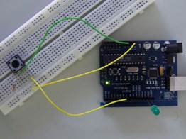
Button1 |
Button The pushbutton is a component that
connects two points in a circuit when you press it. The example turns on an
LED when you press the button. We connect three wires to the
Arduino board. The first goes from one leg of the pushbutton through a
pull-up resistor (here 2.2 KOhms) to the 5 volt
supply. The second goes from the corresponding leg of the pushbutton to
ground. The third connects to a digital i/o pin (here pin 7) which reads the
button's state. When the pushbutton is open (unpressed) there is no
connection between the two legs of the pushbutton, so the pin is connected to
5 volts (through the pull-up resistor) and we read a HIGH. When the button is closed (pressed), it makes a connection between its two
legs, connecting the pin to ground, so that we read a LOW. (The pin is still
connected to 5 volts, but the resistor in-between them
means that the pin is "closer" to ground.) You can also wire this circuit
the opposite way, with a pull-down resistor keeping the input LOW, and going
HIGH when the button is pressed. If so, the behavior of the sketch will be reversed, with the LED normally on and turning off
when you press the button. If you disconnect the digital
i/o pin from everything, the LED may blink erratically. This is because the input is "floating" - that is, it will
more-or-less randomly return either HIGH or LOW. That's
why you need a pull-up or pull-down resister in the circuit. |
|
||||||||||
|
Button1 |
BOTÃO O botão é um
componente que conecta dois pontos de um circuito quando pressionado. Exemplo acende um
LED quando pressiona o botão. Conectamos três
fios à placa Arduino. 1º (Power – 5v ) A primeira vai de uma das pernas
do botão de pressão através de uma resistência de pull-up (aqui 2,2 Kohms)
para a alimentação de 5 volt. 2º (Power – GND) A segunda vai da perna
correspondente do botão de pressão para a terra. 3º (Digital 7) – O terceiro conecta a um I / O
digital pin (aqui pino 7), que lê o estado do botão. Quando o botão é (unpressed) não há nenhuma conexão entre as duas pernas do
botão de pressão, de modo que o pino está ligado a 5 volts (através do
resistor de pull-up) e lemos uma ALTA. Quando o
botão está fechado (pressionado), faz uma conexão entre suas duas pernas,
ligando o pino de terra, de modo que nós lemos um LOW. (O pino ainda está
ligado a 5 volts, mas a resistência entre eles significa que o pino está
"mais perto" para a terra.) Também pode ligar
este circuito o caminho oposto, com um resistor de pull-down mantendo o baixo uso de
insumos, e indo ALTA quando o botão é pressionado. Se assim for, o
comportamento do esboço será revertida, com o LED normalmente ligado e
desligar quando você pressionar o botão. Se você
desconectar o digital de i / o pino de tudo, o LED pode piscar de forma
irregular. Isto é porque a entrada é "flutuante" - ou seja, ele
voltará mais ou menos aleatoriamente alto ou baixo. É por isso que você
precisa de um pull-up ou pull-down
resister no circuito |
|
||||||||||
|
Button1 |
int ledPin = 13; // choose the pin for the LED int inPin = 2; // choose the input pin (for a pushbutton) int val = 0; // variable for reading the pin status void setup() { pinMode(ledPin, OUTPUT); // declare LED as output pinMode(inPin, INPUT); // declare pushbutton as
input } void loop(){ val = digitalRead(inPin); // read
input value if (val == HIGH) { // check if the input is
HIGH (button released) digitalWrite(ledPin, LOW); // turn LED OFF } else { digitalWrite(ledPin, HIGH); // turn LED ON } } |
|
||||||||||
|
|
|
|
||||||||||
|
|
Debounce This example demonstrates the use of a pushbutton as
a switch: each time you press the button, the LED (or whatever) is turned on
(if it's off) or off (if on). It also debounces the input, without which pressing the button
once would appear to the code as
multiple presses. Makes use of the millis() function to keep track of the time when the button is
pressed. Circuit A push-button on pin 7 and an LED on pin 13. Code int inPin = 7; // the number of the input pin int outPin = 13; // the number of the output pin int state = HIGH;
// the current state of the output pin int reading;
// the current reading from the input pin int previous =
LOW; // the previous reading from the input pin // the follow variables are long's because the time, measured in miliseconds, // will quickly become a bigger number than can be stored in an int. long time = 0; // the last time the output pin was toggled long debounce = 200; // the debounce time, increase if the output flickers void setup() { pinMode(inPin, INPUT); pinMode(outPin, OUTPUT); } void loop() { reading = digitalRead(inPin); // if we just pressed the button (i.e. the input went from LOW to
HIGH), // and we've waited long enough since the
last press to ignore any noise... if (reading == HIGH && previous == LOW && millis() - time > debounce)
{ // ... invert the output if (state == HIGH) state = LOW; else state = HIGH; // ... and remember when the last button press was time = millis(); } digitalWrite(outPin, state); previous = reading; } |
|
||||||||||
|
|
|
|
||||||||||
|
|
|
|
||||||||||
|
|
/* Fade This example
shows how to fade an LED on pin 9 using the
analogWrite() function. This example
code is in the public domain. */ int led = 9; // the pin that the LED is
attached to int brightness = 0; // how bright the LED is int fadeAmount = 5; // how many points to fade the LED by // the setup routine runs once when you press reset: void setup()
{ // declare
pin 9 to be an output: pinMode(led, OUTPUT); } // the loop routine runs over and over again
forever: void loop() {
// set the
brightness of pin 9:
analogWrite(led, brightness);
// change
the brightness for next time through the loop: brightness =
brightness + fadeAmount; // reverse
the direction of the fading at the ends of the fade: if
(brightness == 0 || brightness == 255) { fadeAmount
= -fadeAmount ; } // wait for
30 milliseconds to see the dimming effect
delay(30); } |
|
||||||||||
|
|
|
|
||||||||||
|
|
Loop We also call this example "Knight Rider" in memory to a
TV-series from the 80's where the famous David Hasselhoff had an AI machine driving his Pontiac. The car had been augmented with plenty
of LEDs in all possible sizes performing flashy effects. Thus we decided that in order to learn more about sequential
programming and good programming techniques for the I/O board, it would be interesting to use the Knight Rider as a
metaphor. This example makes use of 6 LEDs connected to the pins 2 - 7 on the
board using 220 Ohm resistors. The first code example will make the LEDs blink in a sequence, one by one using only digitalWrite(pinNum,HIGH/LOW)
and delay(time). The second example shows how to use a for(;;) construction to
perform the very same thing, but in fewer lines. The third and last example concentrates in the visual effect of turning the LEDs
on/off in a more softer way. Circuit Code int timer = 100; // The higher the number, the slower the timing. int pins[] = { 2, 3, 4, 5, 6, 7 }; // an array of pin numbers int num_pins = 6; // the number of pins (i.e. the length of the array) void setup() { int i; for (i = 0; i < num pins; i++) // the array elements are numbered
from 0 to num pins - 1 pinMode(pins[i], OUTPUT); // set each pin as an output } void loop() { int i; for (i = 0; i < num_pins; i++) { // loop through each pin... digitalWrite(pins[i], HIGH); // turning it on, delay(timer); // pausing, digitalWrite(pins[i], LOW); // and turning it off. } for (i = num_pins
- 1; i >= 0; i--) { digitalWrite(pins[i], HIGH); delay(timer); digitalWrite(pins[i],
LOW); } } |
|
||||||||||
|
|
|
|
||||||||||
|
Entrada Analógica
– potenciómetro
(Ler+)
Um potenciómetro (português
europeu) é um componente eletrônico que possui resistência elétrica
ajustável. Geralmente, é um resistor de três terminais onde a conexão central
é deslizante e manipulável. Se todos os três terminais são usados, ele atua
como um divisor de tensão |
|
|||||||||||
|
Exer
Pot1 |
Exer Pot1 com
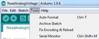
potenciómetro saída de dados Examples > 01.
Basics > ReadAnalogVoltage Entrada Analógica Um potenciômetro é um botão simples que fornece uma resistência
variável, que se pode ler na placa Arduino como um valor análogo. Neste exemplo, o valor controla a taxa em que um LED pisca. Conectamos três fios à placa Arduino. 1º (Power – GND) - O primeiro vai para a terra (GND) de um dos
pinos externos do potenciômetro; 2º (Power – 5v) o segundo vai de 5 volts para o outro pino exterior
do potenciómetro. 3º (Analog in – A2) O terceiro vai de entrada analógica 4º (Tools – Serial
Monitor) NOTA: Atenção à entrada da porta analógica |
|
||||||||||
|
Exer
Pot2 |
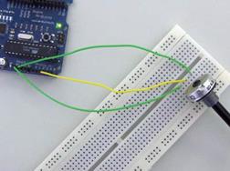
Exer Pot2 -
Entrada Analógica 1º (Power – GND) - O primeiro vai para a terra (GND) de um dos
pinos externos do potenciômetro; 2º (Power – 5v) o segundo vai de 5 volts para o outro pino
exterior do potenciómetro. 3º (Analog in – A2) O terceiro vai de entrada analógica 2 ao
pino do meio do potenciômetro.
Ao girar o veio do potenciómetro, altera a quantidade de resistência em
ambos os lados do limpador o qual está ligado no pino central do
potenciômetro. Isso muda a " proximidade " relativa do pino de 5
volts e terra, dando-nos um entrada analógica diferente. Quando o eixo está
um lado, há 0 volts no pino, e lemos 0. Quando o eixo virado para o lado
contrário, há 5 volts no pino e lemos 1023. AnalogRead ( ) retorna um número
entre 0 e 1023 , que é proporcional à quantidade de tensão que está a ser
aplicada ao pino. |
|
||||||||||
|
|
|
|
||||||||||
|
Exer Pot3 fade |
/* POT to LED test -> by Owen Mundy March
11, 2010
from: http://itp.nyu.edu/physcomp/Labs/AnalogIn —————————————————————*/ int potPin = 0; // Analog input pin that the
potentiometer is attached to int potValue = 0; // value read from the pot int led = 9; // PWM pin that the LED is on. n.b. PWM 0 is on digital pin 9 void setup() { //
initialize serial communications at 9600 bps: Serial.begin(9600); //
declare the led pin as an output:
pinMode(led, OUTPUT); } void loop() {
potValue = analogRead(potPin); // read the pot value
analogWrite(led, potValue/4);
// PWM the LED with the pot value (divided by 4 to fit in a byte) Serial.println("hello"); // print the pot value back to the
debugger pane
delay(10);
// wait 10 milliseconds before the next loop } |
http://owenmundy.com/blog/2010/05/fading-an-led-with-pwm-and-a-potentiometer/ |
||||||||||
|
|
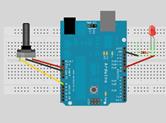
Analog Input A potentiometer is a simple knob that
provides a variable resistance, which we can read into the Arduino board as an
analog value. In this example, that value controls the rate at which an LED
blinks. We connect three wires to the Arduino board. The first goes to ground
from one of the outer pins of the potentiometer. The second goes from 5 volts
to the other outer pin of the potentiometer. The third goes from analog input
2 to the middle pin of the potentiometer. By turning the shaft of the
potentiometer, we change the amount of resistence on either side of the wiper
which is connected to the center pin of the potentiometer. This
changes the relative "closeness" of that pin to 5 volts and ground,
giving us a different analog input. When the shaft is turned all the way in
one direction, there are 0 volts going to the pin, and we read 0. When the
shaft is turned all the way in the other direction, there are 5 volts going
to the pin and we read 1023. In between, analogRead() returns a number
between 0 and 1023 that is proportional to the amount of voltage being
applied to the pin. Code /* * AnalogInput * by DojoDave <http://www.0j0.org> * * Turns on and off a light emitting diode(LED) connected to digital * pin 13. The amount of time the LED will be on and off depends on * the value obtained by analogRead(). In the easiest case we connect * a potentiometer to analog pin 2. */ int potPin = 2; // select the input pin for the potentiometer int ledPin = 13; // select the pin for the LED int val = 0; // variable to store the value coming from the sensor void setup() { pinMode(ledPin, OUTPUT); // declare the ledPin as an OUTPUT } void loop() { val = analogRead(potPin); // read the value from the sensor digitalWrite(ledPin, HIGH); // turn the ledPin on delay(val); // stop the program for some time digitalWrite(ledPin, LOW); // turn the ledPin off delay(val); // stop the program for some time } |
|
||||||||||
|
|
|
|
||||||||||
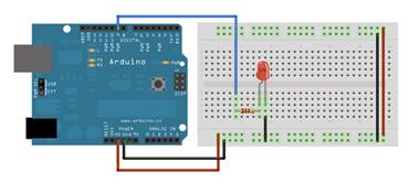
|
|
Fading Demonstrates the use of analog output (PWM) to fade an LED. Circuit An LED connected to digital pin 9. Code int value = 0; // variable to keep the actual value int ledpin = 9; // light connected to digital pin 9 void setup() { // nothing for setup } void loop() { for(value = 0 ; value <= 255; value+=5) // fade in (from min to
max) { analogWrite(ledpin, value); // sets the value (range from 0 to 255) delay(30); // waits for 30 milli seconds to see the dimming effect } for(value = 255; value >=0; value-=5) // fade out (from max to min) { analogWrite(ledpin,
value); delay(30); } } |
|
||||||||||
|
|
Pag 20 |
|

|
|
LOOP |
|
|||||||||||||||
|
15 |
Acender de leds sequencial - este exemplo faz com que 6 leds conectados
aos pinos 2 a 7 6 led 6
Resistencias de 220 Recurso
de programação digitalWrite(pinNum,HIGH/LOW) and delay(time We also
call this example "Knight Rider" in memory to a TV-series from the
80's where the famous David Hasselhoff had an AI machine driving his Pontiac.
The car had been augmented with plenty of LEDs in all possible sizes
performing flashy effects. Thus we decided that in order to learn more about
sequential programming and good programming techniques for the I/O board, it
would be interesting to use the Knight Rider as a metaphor. This
example makes use of 6 LEDs connected to the pins 2 - 7 on the board using
220 Ohm resistors. The first code example will make the LEDs blink in a
sequence, one by one using only digitalWrite(pinNum,HIGH/LOW) and delay(time).
The second example shows how to use a for(;;) construction to perform
the very same thing, but in fewer lines. The third and last example concentrates
in the visual effect of turning the LEDs on/off in a more softer way. Code int
timer = 100; // inicializar o timer quanto maior o nº mais tempo demora)The
higher the number, the slower the timing. int
pins[] = { 2, 3, 4, 5, 6, 7 }; // definição dos pins de saída - an array of
pin numbers int
num_pins = 6; // difine o nº de pins - the number of pins (i.e. the length of
the array) void
setup() { int i; for (i = 0; i < num pins; i++) // Para i =0 até i
nmpins i++ incrementa 1) the array elements are numbered from 0 to num pins - 1 pinMode(pins[i], OUTPUT); //
define os pins para otput set each pin as an output } void
loop() { int i; for (i
= 0; i < num_pins; i++) { // loop through each pin... digitalWrite(pins[i],
HIGH); // turning it on, delay(timer);
// pausing, digitalWrite(pins[i],
LOW); // and turning it off. } for (i = num_pins - 1; i >= 0;
i--) { digitalWrite(pins[i],
HIGH); delay(timer); digitalWrite(pins[i], LOW); } } |
|
|||||||||||||||
|
|
Imprime os caracteres ascii Não é necessário circuito, apenas
software + ferramenta serial print do arduino Demonstrates the advanced serial
printing functions by generating a table of characters and their ASCII values
in decimal, hexadecimal, octal, and binary. Circuit None, but
the Arduino has to be connected to the computer. Code //
ASCII Table // by
Nicholas Zambetti <http://www.zambetti.com> void
setup() { Serial.begin(9600); //
prints title with ending line break Serial.println("ASCII
Table ~ Character Map"); // wait
for the long string to be sent delay(100); } int
number = 33; // first visible character '!' is #33 void
loop() { Serial.print(number,
BYTE); // prints value unaltered, first will be '!' Serial.print(",
dec: "); Serial.print(number);
// prints value as string in decimal (base 10) //
Serial.print(number, DEC); // this also works Serial.print(",
hex: "); Serial.print(number,
HEX); // prints value as string in hexadecimal (base 16) Serial.print(",
oct: "); Serial.print(number,
OCT); // prints value as string in octal (base 8) Serial.print(",
bin: "); Serial.println(number,
BIN); // prints value as string in binary (base 2) // also
prints ending line break // if
printed last visible character '~' #126 ... if(number
== 126) { // loop
forever while(true)
{ continue; } } number++;
// to the next character delay(100);
// allow some time for the Serial data to be sent } Output ASCII
Table ~ Character Map !, dec:
33, hex: 21, oct: 41, bin: 100001 ",
dec: 34, hex: 22, oct: 42, bin: 100010 #, dec:
35, hex: 23, oct: 43, bin: 100011 $, dec:
36, hex: 24, oct: 44, bin: 100100 %, dec:
37, hex: 25, oct: 45, bin: 100101 &,
dec: 38, hex: 26, oct: 46, bin: 100110 ', dec:
39, hex: 27, oct: 47, bin: 100111 (, dec: 40, hex: 28, oct: 50, bin: 101000 |
|
|||||||||||||||
|
|
Examples > Communication Dimmer Enviar dados do computador para o
arduino – neste caso controlar a intensidade de luz de um led Demonstrates the sending data from the
computer to the Arduino board, in this case to control the brightness of an
LED. The data is sent in individual bytes, each of which ranges from 0 to
255. Arduino reads these bytes and uses them to set the brightness of the
LED. Circuit An LED connected to pin 9 (with
appropriate resistor). Code int
ledPin = 9; void
setup() { //
begin the serial communication Serial.begin(9600); pinMode(ledPin,
OUTPUT); } void
loop() { byte
val; //
check if data has been sent from the computer if
(Serial.available()) { // read
the most recent byte (which will be from 0 to 255) val =
Serial.read(); // set
the brightness of the LED analogWrite(ledPin,
val); } } Processing Code //
Dimmer - sends bytes over a serial port // by
David A. Mellis import
processing.serial.*; Serial
port; void
setup() { size(256,
150); println("Available
serial ports:"); println(Serial.list()); // Uses
the first port in this list (number 0). Change this to //
select the port corresponding to your Arduino board. The last // parameter
(e.g. 9600) is the speed of the communication. It // has
to correspond to the value passed to Serial.begin() in your //
Arduino sketch. port =
new Serial(this, Serial.list()[0], 9600); // If
you know the name of the port used by the Arduino board, you // can
specify it directly like this. //port
= new Serial(this, "COM1", 9600); } void
draw() { // draw
a gradient from black to white for
(int i = 0; i < 256; i++) { stroke(i); line(i,
0, i, 150); } //
write the current X-position of the mouse to the serial port as // a
single byte port.write(mouseX); |
|
|||||||||||||||
|
|
Examples > Communication Graph Do
arduino para o computador A simple example of communication from
the Arduino board to the computer: the value of an analog input is printed.
We call this "serial" communication because the connection appears
to both the Arduino and the computer as an old-fashioned serial port, even
though it may actually use a USB cable. You can use the Arduino serial monitor
to view the sent data, or it can be read by Processing (see code below),
Flash, PD, Max/MSP, etc. Circuit An analog input connected to analog
input pin 0. Code void
setup() { Serial.begin(9600); } void
loop() { Serial.println(analogRead(0)); delay(20); } Processing Code //
Graph // by
David A. Mellis // //
Demonstrates reading data from the Arduino board by graphing the //
values received. // //
based on Analog In // by
<a href="http://itp.jtnimoy.com">Josh Nimoy</a>. import
processing.serial.*; Serial
port; String
buff = ""; int
NEWLINE = 10; //
Store the last 64 values received so we can graph them. int[]
values = new int[64]; void
setup() { size(512,
256); println("Available
serial ports:"); println(Serial.list()); // Uses
the first port in this list (number 0). Change this to //
select the port corresponding to your Arduino board. The last //
parameter (e.g. 9600) is the speed of the communication. It // has to
correspond to the value passed to Serial.begin() in your //
Arduino sketch. port =
new Serial(this, Serial.list()[0], 9600); // If
you know the name of the port used by the Arduino board, you // can
specify it directly like this. //port
= new Serial(this, "COM1", 9600); } void
draw() { background(53); stroke(255); //
Graph the stored values by drawing a lines between them. for
(int i = 0; i < 63; i++) line(i
* 8, 255 - values[i], (i + 1) * 8, 255 - values[i + 1]); while
(port.available() > 0) serialEvent(port.read()); } void
serialEvent(int serial) { if
(serial != NEWLINE) { //
Store all the characters on the line. buff +=
char(serial); } else
{ // The
end of each line is marked by two characters, a carriage //
return and a newline. We're here because we've gotten a newline, // but
we still need to strip off the carriage return. buff =
buff.substring(0, buff.length()-1); //
Parse the String into an integer. We divide by 4 because //
analog inputs go from 0 to 1023 while colors in Processing // only
go from 0 to 255. int val
= Integer.parseInt(buff)/4; //
Clear the value of "buff" buff =
""; //
Shift over the existing values to make room for the new one. for
(int i = 0; i < 63; i++) values[i]
= values[i + 1]; // Add
the received value to the array. values[63] = val; } } |
|
|||||||||||||||
|
|
Examples > Communication Physical Pixel Do pc para o arduino – neste caso
acende o led quando carregamos em H e apaga em L An example of using the Arduino board
to receive data from the computer. In this case, the Arduino boards turns on
an LED when it receives the character 'H', and turns off the LED when it
receives the character 'L'. The data can be sent from the Arduino serial
monitor, or another program like Processing (see code below), Flash (via a
serial-net proxy), PD, or Max/MSP. Circuit An LED on pin 13. Code int
outputPin = 13; int
val; void
setup() { Serial.begin(9600); pinMode(outputPin,
OUTPUT); } void
loop() { if
(Serial.available()) { val =
Serial.read(); if (val
== 'H') { digitalWrite(outputPin,
HIGH); } if (val
== 'L') { digitalWrite(outputPin,
LOW); } } } Processing Code //
mouseover serial // by
BARRAGAN <http://people.interaction-ivrea.it/h.barragan> //
Demonstrates how to send data to the Arduino I/O board, in order to // turn
ON a light if the mouse is over a rectangle and turn it off // if
the mouse is not. //
created 13 May 2004 import
processing.serial.*; Serial
port; void
setup() { size(200,
200); noStroke(); frameRate(10); // List
all the available serial ports in the output pane. // You
will need to choose the port that the Arduino board is //
connected to from this list. The first port in the list is // port
#0 and the third port in the list is port #2. println(Serial.list()); // Open
the port that the Arduino board is connected to (in this case #0) // Make
sure to open the port at the same speed Arduino is using (9600bps) port =
new Serial(this, Serial.list()[0], 9600); } //
function to test if mouse is over square boolean
mouseOverRect() { return
((mouseX >= 50)&&(mouseX <= 150)&&(mouseY >=
50)&(mouseY <= 150)); } void
draw() { background(#222222); if(mouseOverRect())
// if mouse is over square { fill(#BBBBB0);
// change color port.write('H');
// send an 'H' to indicate mouse is over square } else
{ fill(#666660);
// change color port.write('L');
// send an 'L' otherwise } rect(50, 50, 100, 100); // draw
square } |
|
|||||||||||||||
|
|
Virtual Color Mixer Do
arduino para o PC – neste caso informação de 3 potenciómetros Demonstrates one technique for sending
multiple values from the Arduino board to the computer. In this case, the
readings from three potentiometers are used to
set the red, green, and blue components of the background color of a
Processing sketch. Circuit Potentiometers connected to analog
input pins 0, 1, and 2. Code int
redPin = 0; int
greenPin = 1; int
bluePin = 2; void
setup() { Serial.begin(9600); } void
loop() { Serial.print("R"); Serial.println(analogRead(redPin)); Serial.print("G"); Serial.println(analogRead(greenPin)); Serial.print("B"); Serial.println(analogRead(bluePin)); delay(100); } Processing Code /** * Color
Mixer * by
David A. Mellis * *
Created 2 December 2006 * * based
on Analog In * by
<a href="http://itp.jtnimoy.com">Josh Nimoy</a>. * *
Created 8 February 2003 *
Updated 2 April 2005 */ import
processing.serial.*; String
buff = ""; int
rval = 0, gval = 0, bval = 0; int
NEWLINE = 10; Serial
port; void
setup() { size(200,
200); //
Print a list in case COM1 doesn't work out println("Available
serial ports:"); println(Serial.list()); //port
= new Serial(this, "COM1", 9600); // Uses
the first available port port =
new Serial(this, Serial.list()[0], 9600); } void
draw() { while (port.available()
> 0) { serialEvent(port.read()); } background(rval,
gval, bval); } void
serialEvent(int serial) { // If
the variable "serial" is not equal to the value for // a
new line, add the value to the variable "buff". If the //
value "serial" is equal to the value for a new line, // save
the value of the buffer into the variable "val". if(serial
!= NEWLINE) { buff +=
char(serial); } else
{ // The
first character tells us which color this value is for char c
= buff.charAt(0); //
Remove it from the string buff =
buff.substring(1); //
Discard the carriage return at the end of the buffer buff =
buff.substring(0, buff.length()-1); //
Parse the String into an integer if (c
== 'R') rval =
Integer.parseInt(buff); else if
(c == 'G') gval =
Integer.parseInt(buff); else if
(c == 'B') bval =
Integer.parseInt(buff); //
Clear the value of "buff" buff = ""; } } |
|
|||||||||||||||
|
|
Read Two Switches With One I/O Pin There are handy 20K pullup resistors
(resistors connected internally between Arduino I/O pins and VCC - +5 volts
in the Arduino's case) built into the Atmega
chip upon which Freeduino's are based. They are accessible from software by
using the digitalWrite() function, when the pin
is set to an input. This sketch exploits the pullup
resistors under software control. The idea is that an external 200K resistor
to ground will cause an input pin to report LOW when
the internal (20K) pullup resistor is turned off. When the internal pullup
resistor is turned on however, it will overwhelm
the external 200K resistor and the pin will report HIGH. One downside of the scheme (there
always has to be a downside doesn't there?) is that one can't tell if both
buttons are pushed at the same time. In this case
the scheme just reports that sw2 is pushed. The job of the 10K series
resistor, incidentally, is to prevent a short
circuit if a pesky user pushes both buttons at once. It can be omitted on a
center-off slide or toggle switch where the states are
mutually exclusive. /* *
Read_Two_Switches_On_One_Pin * Read
two pushbutton switches or one center-off toggle switch with one Arduino pin * Paul
Badger 2008 * From
an idea in EDN (Electronic Design News) * *
Exploits the pullup resistors available on each I/O and analog pin * The
idea is that the 200K resistor to ground will cause the input pin to report
LOW when the * (20K)
pullup resistor is turned off, but when the pullup resistor is turned on, * it
will overwhelm the 200K resistor and the pin will report HIGH. * * Schematic
Diagram ( can't belive I drew this funky ascii schematic ) * * * +5 V * | * \ * / * \ 10K * / * \ * | * /
switch 1 or 1/2 of center-off toggle or slide switch * / * | *
digital pin ________+_____________/\/\/\____________ ground * | * | 200K
to 1M (not critical) * / * /
switch 2 or 1/2 of center-off toggle or slide switch * | * | * _____ * ___
ground * _ * */ #define
swPin 2 // pin for input - note: no semicolon after #define int
stateA, stateB; // variables to store pin states int
sw1, sw2; // variables to represent switch states void
setup() { Serial.begin(9600); } void
loop() { digitalWrite(swPin,
LOW); // make sure the puillup resistors are off stateA
= digitalRead(swPin); digitalWrite(swPin,
HIGH); // turn on the puillup resistors stateB
= digitalRead(swPin); if (
stateA == 1 && stateB == 1 ){ // both states HIGH - switch 1 must be
pushed sw1 =
1; sw2 =
0; } else if
( stateA == 0 && stateB == 0 ){ // both states LOW - switch 2 must be
pushed sw1 =
0; sw2 =
1; } else{
// stateA HIGH and stateB LOW sw1 =
0; // no switches pushed - or center-off toggle in middle position sw2 =
0; } Serial.print(sw1); Serial.print("
"); // pad some spaces to format print output Serial.println(sw2); delay(100); } |
|
|||||||||||||||
|
|
|
|
|||||||||||||||
|
|
|
|
|||||||||||||||
|
|
|
|
|||||||||||||||